![]()
|
|
I have a thread on Reef Central (EnglishRebel's 260 Gallon System Build) that shows step-by-step how I planned, constructed, plumbed, wired and equipped my first saltwater reef aquarium and associated filter systems. This article concentrates on one aspect of that build — how I constructed the stand.
Although all the necessary “stuff” is downstairs in the basement equipment room, the display tank was to be situated in our sunroom that I built off the back of our house a few years ago. When I was designing the room, I specified 12” deep x 3” thick laminated wooden beams under the area where the tank was to be located so that the floor would be capable of supporting the tank and it's contents.
The tank measures 60” long x 30” deep x 24” tall and has Starphire® glass on three sides with an external overflow (48” long x 6” deep x 12” high) at the back. I think the vendor (Aquarium Obsessed of Canada) said it weighed in at around 300 lbs. When I started the project of constructing the stand, I wanted to make sure that it was sturdy enough for the heavy tank and contents. I will make one statement here so that those who have constructed stands before, are thinking (quite correctly) that it is way over-engineered. I am a retired engineer, and I tend to be uptight about things that I have little experience with. Not having installed as large a tank as this before, I fully admit that I designed the stand to support one probably three times as heavy!
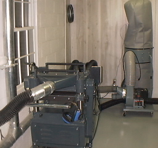
In order to construct a stand you should probably have, at the very least, a basic set of tools. I am fortunate enough to have a woodworking shop to which, over the years, I have added many tools. Here are some photos from the early days (I have rearranged things a little since then).
 |
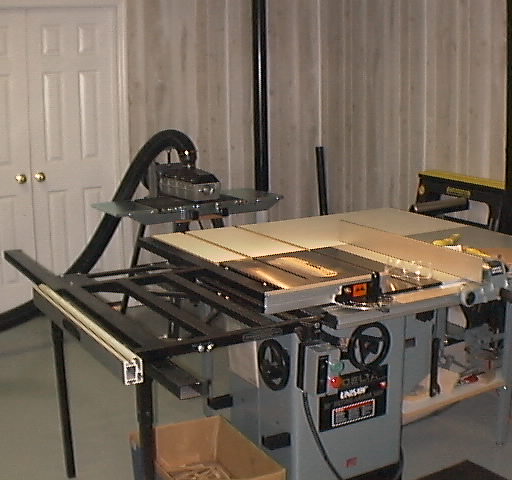 |
| 16" planer | 10" Delta table saw |
 |
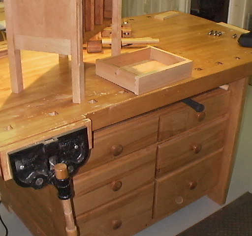 |
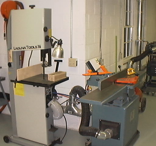
| Bandsaw and 8" jointer | Workbench |
The approach I adopted was to construct the front and back “frames” as one would when building a header for a house to support the weight of the wall, floor and roof above a window or door opening. A header consists of either 2 x 6s, 2 x 8s, or 2 x 12s depending on the span and the load above. I chose to use 2 x 6s as my “span” was only 5'-0".
A header is simply two 2 x 6s nailed together with a piece of ½" plywood placed in between. The plywood is needed because two 2 x 6s together would be 3" wide and the 2 x 4s that the header sits on is 3½" wide. Here’s a simple illustration showing how they all fit together.
   |
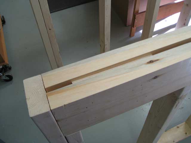
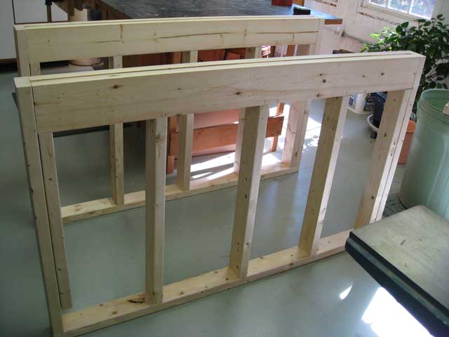
I nailed the 2 x 6s and plywood together to form the top header. The photo (below left) is the assembled header. You can see the plywood spacers in between the 2 x 6s. The plywood does not need to be the same size as the 2 x 6 as it is only a spacer and does nothing for the integrity of the header. The right-hand photo (below) shows the assembled front and back frames. Each frame consists of the aforementioned header with 2 x 4s underneath, located at the bottom where it sits on the floor, and at each end. One thing that you will notice in the left-hand photo is that the tops of the 2 x 6s appear to be flat and not rounded on the edges like a regular 2 x 6. I ran the top edges of the 2 x 6s through my jointer so that the top would be perfectly flat. There is no compelling reason to do this, but as I have a jointer, it was no big deal.
 |
 |
The next task was to attach the two frames to each other. At the top where the load would be, I used 2 x 6 cross members sitting in joist hangers attached to the frames. I like to use joist hangers, as they are much stronger than simply nailing or screwing through the frames into the ends of the 2 x 6. You can pick these up from Lowe's or Home Depot — they’re located in the deck hardware section.
Here’s a photo (below) of the completed frame. The joist hangers are clearly visible. The stand's overall size is 60" long x 30" deep. At the bottom, where there is no load, I used 2 x 4s to space the frames the correct distance apart. The end frames are simply a 2 x 6 at the top that’s screwed into the headers with 2 x 4s under it that are attached to the end 2 x 4 of the frame. You could probably park a Hummer on this thing!
 |
| Completed stand frame in my shop. |
The next job was to put on a plywood top and screw it down to the frames and cross members. I used ¾" A/C plywood. For those of you not familiar with plywood grading, the letter grades typically come in pairs, where one letter refers to the "better" side, called the face, and the other letter to the back side, opposite the face. As such, a sheet of A-C plywood will be very well finished on the face with a relatively unfinished back. Conversely, construction grade plywood would be C-D (commonly referred to as CDX plywood), which is great for structural use but not suited to be finish material.
You could use furniture grade plywood (A/A) but that would be too expensive; while it may serve to provide additional structural integrity due to it’s construction, A/C grade is perfectly adequate. If you want to beef up the stand, then two layers of ¾" A/C plywood could be used.
 |
In the photo above you can see that I’ve moved the frame upstairs to its final position. The stand is positioned about 8" off the back wall because, as I mentioned earlier, my tank has a 6" deep external overflow. On the left you can see the plumbing that comes up from my equipment room located downstairs in the basement. My ever-dutiful wife asked how I was going to conceal them. My reply was that a potted plant would look nice in that spot. As you can imagine, that didn’t go down well, and you will see later how I covered the pipes and kept my marriage intact.
One thing to note is that if your stand is larger than a doorway (mine was 30" deep x 30" tall), it's a good idea to make sure that you have the ability to break it down into manageable pieces. I carried the front and back frames upstairs (which were quite heavy) where I installed the cross members into the joist hangers and attached the end frames. I then added the piece of ¾" A/C plywood — screwing it down securely with rust resistant screws. Do not use drywall screws on any of the frame joints. Drywall screws can break quite easily and are not intended to have any structural integrity. I used coated deck screws throughout.
You will see that I added a 2 x 6 diagonal brace at the back to ensure that the stand did not “rack.” I also made sure that the top was absolutely level. For this, I would strongly recommend a good quality four-foot level. One of those “torpedo” levels will really not cut it, and it's very important for the stand to be level. I had to shim the right-hand end about ¼" with wooden shims that I got at Lowe's. The best thing about the way I constructed my stand with the headers is that it is so strong that I could just shim up the stand at the end as the header distributes the load to each end. I could even have left out the intermediate 2 x 4 “studs,” and it would have been just fine. However, adding a couple of intermediate studs was no big deal or cost and this provides a place to attach the outer panels. Having said that, if I had to do it again, I would leave out that center stud in the front, as it would make getting under the stand a lot easier. As you will see later, I have two access doors in the front, and that center stud makes it a real squeeze to get through (and I’m by no means a large person).
My wife insisted that the stand look like a piece of furniture, so “skinning” the stand with plywood and slapping on a coat of paint was not an option. I like working with mahogany as it’s easy to machine, doesn’t tend to warp or twist and takes a nice finish. So I went off to my local hardwood supplier and picked up about 50 board feet of 4/4 mahogany. 4/4 lumber (pronounced ‘four quarter’) is just that — four quarters of an inch or 1" thick. For those who are not familiar with wood sizes, a board foot is a piece of wood that is 1" thick x 12" wide x 12" long. So a piece that is say, 8' long x 6" wide x 1" thick, is 4 board feet.
The lumber I bought was not finished. In other words it’s as it comes from the sawmill — rough on all four sides. I could have asked the hardwood supplier to plane it on both sides and joint both edges (which is designated as 4S — finished on all four sides), but this would have cost extra. As I have the ability to do this in my shop with my planer and jointer, I purchased the wood unfinished. When I got the lumber home, I proceeded to run all the pieces — first through my planer to clean up the boards and make them all a uniform ¾" thick. I then ran one edge through the jointer to make it straight and smooth, and then I ripped the boards to the correct width on my table saw.
|
I now needed to figure out how to “skin” the frame. I wanted to conceal the ¾" glass bottom of the tank plus the ¾" bottom Eurobracing, so I needed to run a “shelf” around the top of the frame that was 1½" thick.
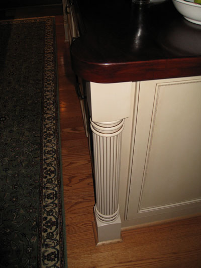
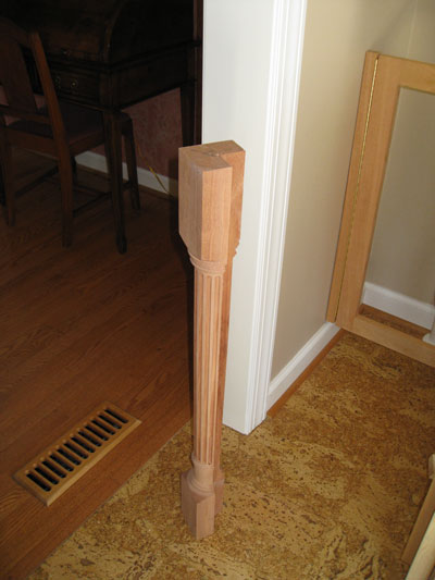
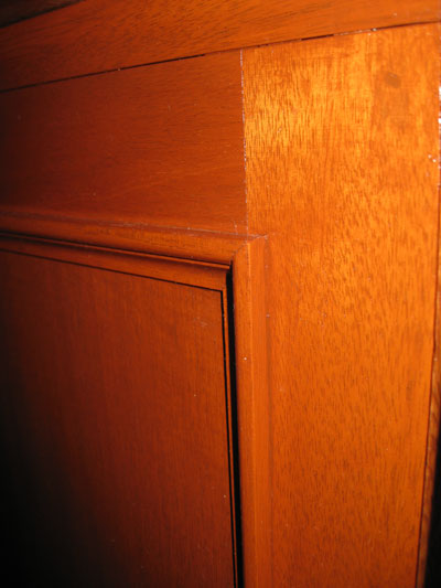
To make the corners look nice I decided to do what I did on the island top in my kitchen remodel a few years ago. Here’s a photo (left) of the top I made. The corner has a round profile that covers the top of the leg.
You can see the decorative “leg” that wraps the corner of the cabinet. My wife liked that, so I decided to do the same for the tank stand. I found an online store that sells all sorts of table legs. I found one that I (well, my wife) liked and for an extra charge they would cut out one quarter of the leg so that it would fit the stand's corners.
I ordered a pair in solid mahogany and in the meantime I figured out how I was going to attach the corner legs and the shelf. As the tank sits all the way up to the stand's edge, I needed a way to support the shelf. To achieve this I attached a piece of solid mahogany banding 2" tall by ¾" thick all the way around the top of the stand — butting into 3" wide x ¾" vertical pieces at each corner. These vertical pieces served two purposes — 1) so that I would have a place to attach the corner legs, and 2) to give a “stop” for the panels so they wouldn’t butt into the legs.
I next needed to make a template for the shelf. Below you can see that I’ve cut out a paper template and positioned it on the corners. I didn’t have the legs yet but knew what size they would be. To the left of the template, you can see the 2" tall by ¾" thick band that will support the shelf.
 |
I was happy with the profile, so I proceeded to make up the shelf which consisted of sections of ¾" thick lumber of various widths — 3" for the main runs and 6" for the corner pieces. After making up the shelf blank, I doubled it up by adding more ¾" pieces so I ended up with a 1½" thick shelf. Next, I cut the profile for the corners on my bandsaw and sanded them smooth.
 |
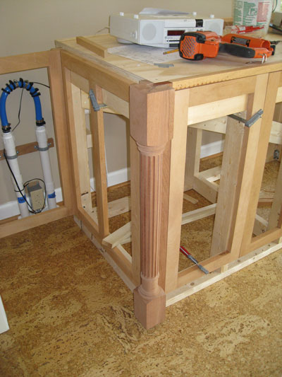 |
By now the corner legs had arrived. As you can see in the left-hand photo above, they cut out one quarter of the leg so it would wrap around the corner of the stand. In the right-hand photo I have fitted one of the legs to the stand. Happy with the way they fitted together, I went on to finish up the panels.
The panels consist of stiles (the vertical pieces) and rails (the horizontal pieces) with ¼" mahogany plywood for the infill. All the panels would be the same height to go from about 2" above the floor to the underside of the piece of wood that supports the shelf. The traditional construction for panels is to have the rails and stiles attached to each other with mortise and tenon joints with a dado (groove) machined into them to accept either a flat or raised panel. This is a time-consuming job and, although I have made furniture before using this method, I needed a total of seven panels, so I looked for a faster way. Check Winn Dixie Ad and Lowe's Ad.
On previous projects (the built-in bookshelves and cupboards in my study) I had made the carcass out of plywood and covered the front edge with a face frame. The face frame is made from rails and stiles, but they are connected to each other with pocket hole joinery rather than mortise and tenon joints. Normally, if you glue a rail to a stile you are butting the end grain of the rail to the cross grain of the stile. Gluing end grain to cross grain does not provide a strong enough joint, but by adding screws to the mix, it makes the joint very strong. While you could just drive a screw through the stile into the end of the rail, it wouldn’t look very nice with its head exposed. There is a better solution — pocket hole joints.
|
I used this jig (left) to create the pocket hole in the rails, which are then glued and screwed to the rails with special screws. It’s a specialized piece of equipment made by Kregg. It’s a jig with a clamp to hold the piece of wood firmly and a series of holes at an angle that have brass bushings to guide a drill bit. The drill bit has a stepped shank with the smaller bit drilling a pilot hole and the larger size drilling a hole for the screw's head.
 |
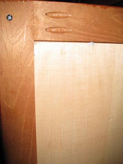
After putting glue on the end of the rail I clamped it to the stile and then drove screws through the pockets created by the jig, into the stile. You can see the hole (right) that’s drilled at an angle. This is the backside of the frame so the pocket holes will not be visible from the front once it's put in place. You can purchase specially shaped “plugs” of the same material as the wood species. These are then glued into the holes, sanded flush and stained. I chose not to do this.
Normally, I would machine a rabbet in the backside of the frame for the infill panel to fit into. In this case I was trying to find a faster way to construct these panels, so I decided to do something a little different. To have a stop that the inserted panel could be secured against and also to dress up the front of the panel, I decided to add a molding around the inside edge of the frame. I couldn’t find a suitable molding in mahogany, so I got a local wood shop to mill up some for me.
 |
You can see that it has a rabbet on the back which will fit over the frame's inside edge. The corners need to be mitered (like a picture frame), and in order to do that I broke out my Jorgensen miter box saw.
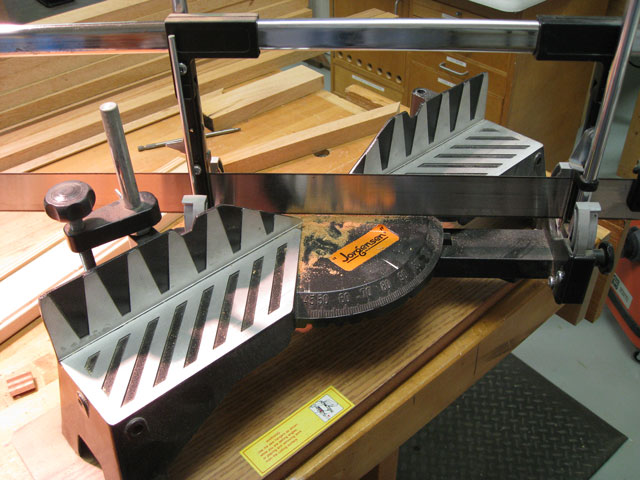 |
| Jorgensen miter box saw. |
It’s nothing more than a glorified miter box, but it has a precise angle adjustment and a very sharp blade that has roller guides to keep it straight.
After cutting all the molding, I fitted it to the frames with glue and pins. I have a pneumatic pin nailer that shoots 5/8" long pins that have no head like a conventional nail. This means that there are no holes to fill, as they are almost invisible. The right hand photo shows the finished molding and inserted panel.
 |
 |
| Back view of panel | Front view of panel |
I could now cut the ¼" mahogany plywood panels to fit into the back of the frames. The molding that I glued earlier provides a stop for the panel to sit against, and I secured them with pushpins (you can just make them out in the left-hand photo above). These are normally used to secure the glass and photos in a picture frame.
|
After making up all of the panels, I fitted them to the frame from the backside. At this time I also fitted the corner legs.
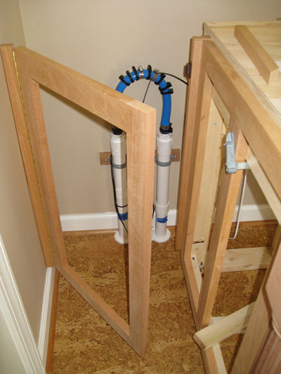
I now needed to finish off the rest of the panels and here (right) you can see where I have fitted a door so I can gain access to the plumbing behind the tank (and keep my wife happy). I fitted all the panels before I added the plywood inserts, as it was easier to clamp them to the support framework to make sure they all fitted properly.
A cleat that I screwed to the wall supports the door, which is hung with a brass piano hinge. I had to shim the cleat so that the door was plumb with the stand as the wall was not (usually the case with most houses). The door closes against a stop that I attached to the stand and is held shut with a magnetic catch purchased from Lowe's.
|
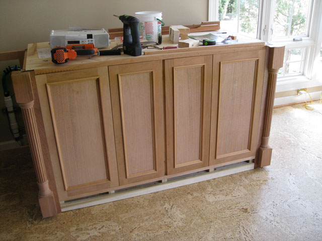
Here is a photo (left) of the completed right-hand end panel installation on the frame. Rather than make two panels, I made a single panel with a center stile. It’s secured to the frame with screws through the back. The white wood you can see at the bottom is poplar to which the base will be attached later. It’s nailed to the 2 x 4 on the bottom of the stand.
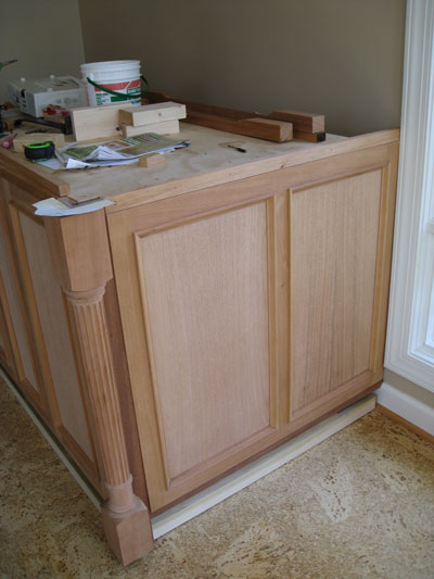
The photo below shows the completed panels on the front of the frame. The two center panels are actually doors that allow access to the electrics and plumbing under the stand. I added another piece of poplar at the bottom to which the base will be attached later.
|
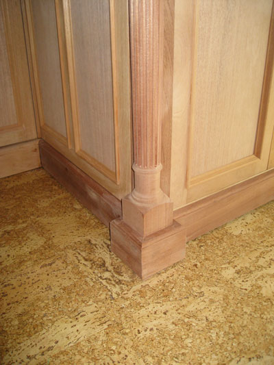
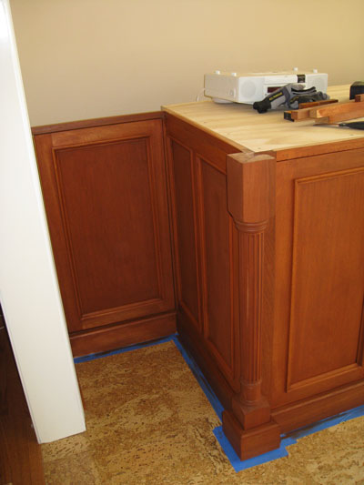
I now moved on to finishing off the base. I added a piece of 3" wide x ¾” thick mahogany all round the stand's bottom. I held it off the floor about ¼” to allow for the gap caused when I shimmed the stand to level it. To close the gap, I got some oak shoe molding from Lowe's and stained it with the cherry stain that I used on the rest of the stand.
You can see here that I wrapped the legs with the base trim. I normally wouldn’t have done that — but just butted the base into the plinth at the bottom of the leg. However, in this case the legs were standard 36" long and as the stand is 36 ¾" (36” for the frame and ¾" for the plywood top), the leg doesn’t reach the floor. The gap was small enough at the left-hand side to cover with the shoe molding, but on the right-hand side it was too large due to having to shim the stand to make it level. I could have ordered custom longer legs but didn’t realize my mistake until they arrived. I call it poor planning on my part. I was now behind the ? and the only solution was to run the base molding all round the leg plinth as shown.
 |
Having completed all of the woodworking, it was time to stain it. My wife wanted a cherry look even though the cabinetry is made from mahogany, but that’s what stains are for - right? Here are some photos of the finished stand panels.
 |
 |
| Left-hand end | Right-hand end |
Here’s a full frontal view of the finished stand with two coats of Varathane Traditional Cherry, oil-based, rub-on stain and three coats of oil-based gloss polyurethane.
 |
|
I then installed some antique brass knobs (photo right) that my wife picked out (actually, the same ones found on our master bathroom cabinets).
Lastly, I built a three-sided surround for the top of the tank to hide the lights and to cover the tank's water line. It’s hinged off the back wall for easy access with stainless steel marine hinges.
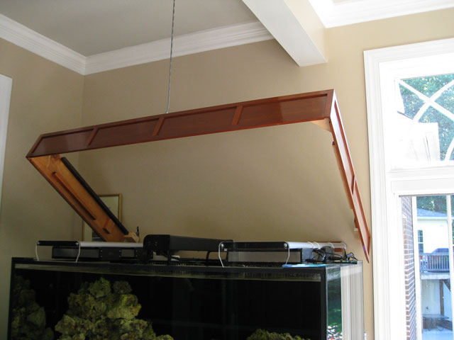 |
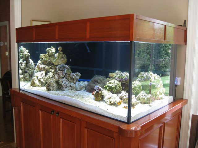
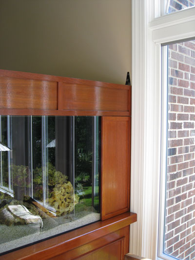
Here’s a photo of the almost finished stand and top surround with the tank installed, filled and running. You can see the shelf that runs around three sides and the corner profile that covers the top of the decorative “legs.” The last job was to close the gaps at the rear of the tank to hide the overflow, Vortech MP 40s, controllers and piping.
 |
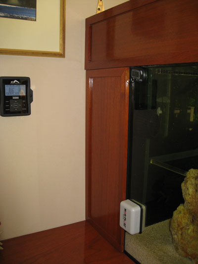
To do this, I made some simple panels from mahogany, stained them and added two coats of polyurethane. They are held in place by magnetic catches.
On the left-hand photo below you can see my ReefKeeper Elite head unit that I use to control the system (pumps, lights, skimmer, pH, etc.). You can just see a shelf at the bottom of the same photo. It is wider than the ones that run around the tank because it covers the piping coming up from the basement equipment room.
 |
 |
I hope you enjoyed reading about how I built my stand, and that it inspires you to do the same. With a little skill, some good tools, a lot of planning, and oodles of patience, anyone can do it — even a caveman!
![]()