

Stats:
 | Today | 2219 |
 | Yesterday | 19722 |
 | This week | 28801 |
 | Last week | 54704 |
 | This month | 52644 |
 | Last month | 217069 |
 | All days | 34066162 |
Your IP: 18.227.111.102
Mozilla 5.0,
Today: May 06, 2025


Calcium Reactors… In, Out and Everything in Between
Part 2
Setting Up the System… Or How to Finally Get to Play With Your New Toy:
There are three potential means to feed water to a reactor, or variations thereof: those feeding methods could be either by gravity, by using a “T”-off of the return pump, by using a peristaltic pump or by using a powerhead to pump water into the reactor.
The use of gravity by just using a hose or tubing to drain water from a higher level into the suction of the recirculation pump can work under the proper circumstances, especially when using a rather large recirculation pump. It has the disadvantage that as the media dissolves or starts getting plugged; the change in recirculation pressure ends up in changes to the effluent rate so using gravity may not provide for a really stable effluent flow.
The second alternative, which is connecting the feed line to a T-off the discharge of the return pump, can also work under the right circumstances but with some caveats. In my early “Dumb Dumb” days I connected my reactor to a T-off from the discharge of my Iwaki 100 RLT return pump pumping water to my tank one floor above. Half an hour later the top of the reactor popped open.
Calcium reactors are not built to really run pressurized. A slight pressure of 2 to 5 psi is about the range they can operate safely. At between 5 to 10 psi most reactors will start leaking and at 10 psi you will be applying 330 pounds of force to the top flange of a 6.5” dia. reactor chamber so anything above that is running the risk of blowing the top or cracking the reactor cylinder.
Moving the effluent valve to the inlet of the reactor while leaving the output fully open is a way to avoid excessive pressure but in doing so you will find out as I did that the effluent flow is not as stable, especially if you feed other devices from the return pump. A bit of debris in the incoming water or changes in the adjustment of any one of those other devices is enough to change the inlet pressure ending up in changes in the effluent flow.
The use of a peristaltic pump to feed the reactor is the method that provides the best effluent flow stability of them all but good peristaltic pumps are not that cheap. You will require a peristaltic pump that provides continuous flow, is specified for a 100% cycle or able to work 100% of the time without stopping and with a flow capacity that is adjustable between 20 and 150 ml/min.
Finally, the best way I have found that provides good effluent flow stability for the money is to feed the reactor by using a power head. A Maxi-Jet 1200 seems to be well suited to do so.
You can connect the reactor inlet line to the discharge of the power head in a couple of different ways.
First, it is important to notice that the power head is designed to pump a lot more water than what the reactor will require so the small volume of water will not provide for proper cooling of the power head and the increase in temperature will promote calcium carbonate precipitation in the power head shaft eventually ceasing the pump rotor and getting it stuck.
 |
To prevent this and also in the interest of providing a more stable pressure in the inlet, I recommend providing an outlet for part of the water so it returns back to the sump thus creating more flow through the power head. To do this is rather simple.
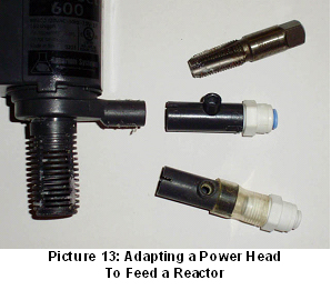
Instead of connecting your feed line directly to the power head outlet, connect the line to the coupling that comes with the power head, the one that has a hole originally to be used for the injection of air to the power head, then just insert the coupling to the power head outlet. For further reference, this is the cylindrical coupling that support the fan like piece used to redirect the power head flow. Remove the fan like piece; cut away the two little pins that support the fan like piece and you will have it ready to insert a hose into it.
You can also use a tap to thread the inside of the coupling and install a John Guest connector to attach a ¼” poly line to it. (see picture 13).
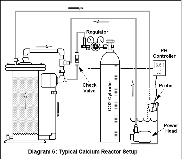
So let’s start with the setup (see diagram 6).
First, select the location for the installation of the reactor. You should have enough room and headspace for the reactor and the CO2 cylinder so they can be close enough to your water source, usually the sump.
The location should be flat and level and at a height that is the same as, or lower than the level of your water source to facilitate bubbles leaving the reactor and for the feed power head to work less in overcoming head pressure. Also, the location should provide for means to tie and secure the CO2 cylinder in a vertical position. Finally, an electrical outlet will be needed nearby.
If the calcium reactor came disassembled, start by assembling the reactor following the manufacturers instruction manual. Usually this implies installing and connecting the recirculation pump as well as the installation of the effluent valve and the recirculation loop. I would recommend applying silicon grease to all the “O” rings for proper sealing and longer life. Use very little grease; once the “O” ring is lubricated, use a paper towel to remove the lubricant from the “O” ring as all that is needed is for the “O” ring to “shine” a little bit.
Rinse the media in a bucket under running water until the water is milky but not dirty. Fill the reactor chamber with media up to the height indicated by the manufacturer, in most cases this will be three quarters of the chamber full or a bit higher.
Secure the cylinder in place, once secured, if the cylinder came with a valve-protecting cap, unscrew and remove the cap. By DOT regulations, all cylinders larger than 20-pound capacity must be fitted with one when the cylinder is moved or transported.
Remove any shrink seals or plastic caps protecting the valve outlet and connect the regulator to the cylinder. Do not forget to use the washer seal. Use the proper wrench to tighten the connection. Using a pipe wrench or a slip wrench may damage the connector.
If your regulator is fitted with a bubble counter, fill the bubble counter with distilled water or glycerin.
 |
Connect the CO2 tubing to the outlet of the bubble counter or to the needle valve if the regulator is not fitted with a counter.
Regardless of how close the cylinder is to the reactor, use at least three feet of CO2 tubing between the regulator and the reactor as some water may flow back into the tubing when closing the regulator.
If you have an in line check valve, cut the tubing at approximately the mid section and connect both ends of the check valve to the tubing. Insure that you have the right orientation for the check valve and that the flow-indicating arrow is pointing toward the reactor side. Most check valves operate better when mounted vertical.
Connect the end of the CO2 line to the CO2 inlet of the reactor at either, the check valve in the reactor if it comes fitted with it or the bubble counter in the reactor if it comes fitted with one and no check valve. If the reactor comes with neither a check valve nor a bubble counter the CO2 inlet is usually located at the suction of the recirculation pump, check the manufacturer manual for the right location of the CO2 inlet connection.
You do not need to fill the bubble counter in the reactor if the regulator is fitted with one. If not, just fill the reactor’s bubble counter with distilled or RO/DI water, do not use glycerin in the reactor’s bubble counter.
Install the water feed power head in a location where it would not suction any bubbles and connect it with tubing to the water inlet of the reactor at the location indicated by the manufacturer instructions.
Finally connect the effluent line from the effluent valve back to the aquarium, usually back to the sump. Insure that the end of the effluent line is not submerged so if CO2 bubbles leave the reactor, those do not bubble under the surface of the aquarium water.
The best location for dripping the effluent is near the suction of the skimmer pump. This will help to improve aeration of the effluent once mixed with the aquarium water and help minimize the pH reducing effect of the effluent by the skimmer aeration aiding in the conversion of carbonic acid into bicarbonate and bicarbonate into carbonate.
If your reactor is not fitted with a pH probe connection then you will need to measure the effluent pH at the point where the effluent returns to the aquarium. To do so, you can hang a plastic cup on the inside wall of the sump. Place the effluent line in a way so the effluent drips into the cup and the cup overflows into the sump. You can place the pH probe in the cup so it will be measuring the effluent pH. Note that this method works only with single chambered reactors. If you have a second chamber you will need to measure the pH at the first chamber so you will need a pH probe connection port in the chamber or in the recirculation loop. As described above you can DIY one as per the instructions given.
Operating and Adjusting the Reactor... Now the Really Fun Part:
In reality it is not difficult to operate and set up a calcium reactor if you become familiar with some basic principles of operation.
Keep in mind the four basic rules of a calcium reactor's operation:
- A calcium reactor adds balanced amounts of calcium and alkalinity. If you start with unbalanced levels, do not expect the reactor to balance the levels back. If the levels start unbalanced, they will remain unbalanced although at a different level.
- A calcium reactor is not meant to increase or adjust the levels, if you try to do so, chances are you will never be able to adjust the reactor properly and you will continue to overshooting your target.
- Your reactor system should be able to maintain a continuous and a stable effluent flow and CO2 bubble rate, if it does not, it will be impossible to operate it properly.
- Be patient, be very patient. The reactor will take several hours to stabilize after any adjustment. Trying to adjust it too often before it has had an opportunity to achieve stability will only make things more difficult and frustrating.
The idea behind adjusting the reactor is rather simple. Because it will add calcium and alkalinity in a balanced way, we are only concerned about adjusting the addition of alkalinity to match the aquarium alkalinity consumption and the calcium in most cases will take care of itself.
Reactor Controls:
There are two main controls for the reactor: the CO2 needle valve used to adjust the amount of CO2 to be added and the effluent valve that is used to adjust the amount of water that passes thru the reactor and is added back to the aquarium.
In general, the more CO2 added, the lower the pH in the reactor will be and the lower the pH in the reactor the higher and faster the dissolution is resulting in more alkalinity in the effluent. The media starts dissolving at a pH of about 7.7. A reactor using aragonite media is usually run at a pH between 6.5 and 6.7. At a pH below 6.5 the media will have a tendency to crumble, turning muddy, so for aragonite my recommendation will be to run the reactor at the stated range. It is important to note that calcite media will require a lower pH, this could be as low as 6.3.
For the effluent control, the higher the effluent flow for a given pH in the reactor, the more alkalinity will be added to the aquarium. Note that changing the effluent flow rate will have an effect on the pH if the amount of CO2 is not changed. When increasing the effluent flow without adding more CO2, the amount of CO2 in proportion to the effluent will be reduced and as a result the pH in the reactor will increase.
So in summary, changing the CO2 rate (bubble rate) will change the pH and amount of alkalinity in the effluent but will not affect the effluent flow. Changing the effluent flow will change the pH, so adjustments to the CO2 rate will be needed if it is desired to maintain the pH level previous to the effluent volume change.
By using these two controls it is possible to adjust the total alkalinity added to the tank so a balance between addition and consumption can be achieved.
There are two different ways to match the reactor’s daily alkalinity supplementation to the daily consumption of alkalinity in the aquarium. Both methods employ trial and error. In other words the reactor is started, the aquarium alkalinity is tested every 24 hours and the reactor is re-adjusted accordingly every 24 hours to increase or reduce the supplementation depending on the results of the tests until the tests show no change in the level of alkalinity in the aquarium.
One method is to adjust the reactor to add a fairly large amount of alkalinity and then connect the solenoid valve to a timer to cut off the supply of CO2 for part of 24 hours, usually at night and adjust the time the CO2 is on until the net addition during the time the CO2 is on, matches the total consumption of the system.
The other method, which seems to be the most popular and the one I use, is to run the reactor continuously and adjust the amount of alkalinity output from the reactor until it matches the alkalinity being consumed.
Running Continuously:
- Calibrate your pH monitor or controller as per the manufacturers instructions. If the reactor is fitted with a probe holder, install the pH probe in the holder and proceed to fill the reactor. Do not allow the probe to dry so proceed with the following steps as soon as the probe has been installed. If you are not using a probe holder, fill the effluent drip cup with some aquarium water and place the pH probe in the cup.
- Fully open the effluent valve.
- Turn on the feed pump or power head and fill the reactor completely with water trying to keep the bubbles inside to a minimum. Trapped bubbles in an effluent line can make the effluent flow unstable.
- Turn on the recirculation pump and insure there is water re-circulating and that the recirculation pump is not running dry.
- Adjust the effluent flow valve to maintain an effluent in accordance to the manufacturers instructions. Note that an effluent flow of below 25 ml/min is not usually that stable and will be difficult to maintain. When running continuously I recommend starting with a fairly low effluent flow and increasing it as required in subsequent steps. 30 ml/min will be a good starting point. To measure the effluent, use the measuring cup to collect the effluent for a period of 1 minute.
- Leave the reactor running without CO2 for 12 hours.
- After 12 hours, measure the effluent flow to insure it is stable and has been maintained. There might be some tendency for the effluent flow to drop a bit, if so readjust the effluent valve back to the 30 ml/min level, do not worry much about precision, anything between 25 to 35 ml/min will work. Wait another 12 hours to insure this time it will be stable.
- After the additional 12 hours if the effluent flow has been maintained then we are ready to start injecting CO2. If the effluent flow is not constant and continues stopping you will need to solve that problem before continuing. (See troubleshooting section).
- Turn on the CO2 using the following sequence. Failing to do so may damage the regulator:
- Wait several hours for the pH in the effluent to stabilize, adjust the CO2 bubble rate so the pH is in between 6.6 and 6.7, increasing the bubble rate if the pH is high or reducing it if the pH is low, make small adjustments at a time or you may end up overshooting and undershooting the pH. Insure also that the bubble rate has been consistent and maintained. If a controller will be used, adjust the CO2 bubble rate to reach a bit lower - 6.4 to 6.5. Wait for the pH to stabilize between adjustments.
- Unplug the solenoid from the power outlet and connect it to the controller if using one. Although the controller will maintain the pH between 6.6 and 6.7, having it adjusted for 6.4 to 6.5 without the controller will insure that even if the controller fails, the pH will not drop too far. Also, limiting the minimum without controller to the 6.4 to 6.5 range, the frequency at which the controller has to turn off and on is reduced, thus reducing the controller and solenoid wear.
a) Close the regulator by unscrewing the pressure-adjusting knob until it feels a bit loose.
b) Use both hands to slowly open the cylinder valve, remember to position yourself or the cylinder in a way that the cylinder valve is between you and the regulator. Continue opening the valve slowly until the high pressure gauge indicates that the maximum pressure has been reached. At this point completely open the cylinder valve. Now there will be pressure in the high-pressure side of the regulator but because the regulator is closed, the delivery pressure gauge should be at zero. If it is not, the regulator may be damaged or defective and must not be used.
Do not attempt to disconnect the regulator while the cylinder valve is open and there is pressure in the high pressure gauge. Before removing the regulator you need to vent that pressure using the following sequence: Close the cylinder valve, disconnect the CO2 tubing from the regulator, open the CO2 needle valve, plug the solenoid into a power outlet to open it, screw in (clockwise) the pressure adjusting knob. The CO2 trapped inside the regulator will be vented through the needle valve. Wait until no pressure is shown on either of the gauges indicating that it is safe to disconnect the regulator. Slowly and partially loosen the connection between the regulator and the cylinder valve while listening for any potential venting of CO2, if so, wait until there is no longer a venting sound before fully disconnecting the regulator from the cylinder.
c) Use soapy water to check for leaks at the connection between the regulator and the cylinder. Do not attempt to fix a leak while there is pressure in the regulator and/or the cylinder valve is open. Follow the sequence described in point (b) above to release the pressure, repair the leak and re-start the process.
d) Slowly screw in (clockwise) the pressure-adjusting knob while observing the delivery pressure gauge reading. The delivery pressure will start to rise. Keep turning the knob until the delivery pressure indicates between 20 to 25 psi. Note that if you exceed the 25 psi, the pressure will not drop back down by unscrewing the knob until the solenoid and the needle valve have been opened and CO2 flow has been established at which time you may use the knob to re-adjust the pressure. If you are using a two-stage regulator, adjust the pressure to only 5 psi.
e) Connect the solenoid valve to a power outlet to open it. A click sound will indicate it actuated.
f) Slowly open the CO2 needle valve until bubbles appear at the bubble counter and CO2 flow has been established. Using the valve, adjust the bubble rate to about 20 bubbles per minute.
g) If using a controller, set up the level at which the CO2 shall open, I would recommend to start at 6.7, if the controller has a span of control I would recommend to set it to the minimum whichis usually about 0.1 pH units so the controller will open the CO2 at 6.7 and close it at 6.6. Do not connect the solenoid to the controller yet.
Test your aquarium alkalinity every 24 hours, if it tends to rise then reduce the CO2 bubble rate, to run the reactor at a higher pH of 6.7 to 6.8, if the alkalinity tends to decrease then increase CO2 bubble rate to reduce the pH in the reactor to a lower range of 6.5 to 6.6.
If using a controller, reset the control point from 6.7 to either 6.8 if alkalinity is increasing or 6.6 if the alkalinity is decreasing as the case may be. Wait for another 24 hours and test the aquarium alkalinity again. If the alkalinity is still increasing, change the pH to 6.9 and wait another 24 hours.
On the other hand, if the alkalinity continues to decrease and because we do not prefer to operate below 6.5, instead of lowering the pH even further, we will increase the effluent rate by about 10 ml/min to 40 ml/min. We will need to increase the CO2 bubble rate proportionally so the pH does not increase with the change in effluent rate and stay at the previous 6.5 level. Repeat this process of testing and adjusting until the alkalinity in the aquarium no longer changes.
If by any chance your aquarium alkalinity has increased too far (a level higher than 4 meq/lt or 11 dKh), just unplug the solenoid to stop the CO2 and wait a couple of days for the alkalinity to be consumed and drop by itself. Then, plug the solenoid back into the outlet or controller and restart the adjustment <> testing cycles.
Throughout the adjustment period, do not be concerned about the alkalinity level as far as it is below the maximum stated, but be concerned with adjusting the reactor so the alkalinity no longer drops or increases, at which point the reactor is adjusted regardless of the level. After the adjustment has been completed you can use some manual supplementation to increase the alkalinity to your targeted level and the reactor will keep it at the new level afterwards.
If, after adjusting the reactor, you want to maintain a lower alkalinity than the one your aquarium ended up with, just unplug the solenoid until the alkalinity drops to your target level and then plug it back in and the reactor will maintain the new level.
You may want to target a calcium level between 380 and 450 ppm and an alkalinity level between 2.5 and 4 meq/lt (7 and 11 dKh) I usually target the middle of the range to have some room for variation or testing error before the level gets out of range.
During the first couple of months you may want to keep testing for alkalinity relatively often; as reliability has been established, and the reactor set up has proven that it is maintaining the level, you can then stretch the time between tests.
Note that the reactor will also be adding calcium and initially you may also need to manually adjust the calcium level using a manual supplement to reach your target. Once there, the reactor will keep it on target.
Finally, although the reactor adds calcium and alkalinity in a balanced way, the consumption may not be balanced due to factors other than coral growth (like nitrification, use of unbalanced salt mix, etc.) so once in a while you may need to make manual adjustments of either calcium or alkalinity as needed to return the chemistry back to balanced targets.
Running with a Timer:
Setting up the reactor to run with a timer is very similar to the steps described above.
Follow steps 1 to 9 above but with these minor differences.
First, for this type of operation, you will not really require a controller unless your CO2 bubble rate is not stable.
In step 5, set up an initial effluent of 50 to 60 ml/min rather than the 30 ml/min.
In step 9(f) adjust the CO2 bubble rate to 50 bubbles per minute instead of the initial 20 bubbles per minute.
10. Wait several hours for the pH in the effluent to stabilize, adjust the CO2 bubble rate so the pH is in between 6.5 and 6.6, increase the rate if the pH is high or reduce it if the pH is low. Insure also that the bubble rate has been consistent and maintained. Wait for the pH to stabilize between adjustments.
11. Unplug the solenoid from the power outlet and connect it to the timer. Set the timer to turn on for 12 hours during the day, maybe this will be, on at 7:00 AM and off at 7:00 PM. Having the reactor operating during the day when the tank pH is the highest will help minimize the reactor’s pH lowering effect.
Test your aquarium alkalinity every 24 hours, if it tends to increase then adjust the timer to reduce the time the CO2 is on, if the alkalinity tends to decrease then adjust the timer to increase the time the CO2 is on.
If by any chance your aquarium alkalinity has increased too far (a level higher than 4 meq/lt or 11 dKh) just unplug the solenoid and wait for the alkalinity to be consumed and drop by itself then plug the solenoid back into the timer but starting with a shorter period of time.
If you reach the point where the reactor is operating with the CO2 on for the 24 hours, then you might need to increase the reactor output. To do so try increasing the CO2 bubble rate to set up a pH in the reactor of 6.4 to 6.5 and if this is not enough you may try to increase both the bubble rate and the effluent rate.
Finally, if despite increasing the reactor output the alkalinity consumption is not met and you still need more addition, the reactor may be undersized. You have several options, either get a larger reactor, or even better yet, complement the reactor with the addition of another form of supplementation. One form I would recommend is dripping limewater (kalkwasser) or a limewater (kalkwasser/Nielsen) reactor as its pH increasing effect helps to counteract the pH lowering effect of the calcium reactor.
Note that you will need to readjust the calcium reactor to compensate for the addition of the second form of supplementation.
Maintaining the Reactor... or Oh no! Do I need to clean it too?
For a long and useful life, simple maintenance of the reactor will suffice. Here is my basic recommendation:
- Top-off the media when about ¼ of it has been consumed. Letting the level of media get too low will reduce the reactor output and performance, the reactor will require re-adjustment and it may increase the pH lowering effect of the reactor.
- Refill the bubble counter with distilled or RO/DI water as necessary.
- Every time the CO2 cylinder is refilled, use a new washer seal between the cylinder valve and the regulator.
- Every two or three months, recalibrate the pH probe. Replace it when it is no longer possible to calibrate properly.
- About every six months:
- Remove the media, rinse it under running water to remove any muddy matter that has accumulated and replace it in the reactor, and then top it off.
- Inspect the recirculation pump impeller for potential wear.
- Inspect and clean the feed pump or power head.
- Clean the whole reactor to remove any salt creep or calcium carbonate incrustations. Using vinegar works well. Pay special attention and make sure to clean the groves for the “O” ring seals.
- Slightly lubricate the “O” rings with silicone grease. Very little is needed.
- Inspect the regulator, solenoid and needle valve for corrosion.
- Every two years, replace all tubing to avoid accumulation of detritus inside.
Troubleshooting... or Now what did I do wrong!
Symptom |
Potential Cause |
Potential Solution |
|
Effluent flow stops dripping or it is difficult to keep it running consistently. |
Obstructed tubing. Improper water feed method. Excessive muddy material in the chamber. Obstructed effluent valve. Effluent valve not precise enough. |
+ Inspect the tubing for potential obstructions, small bubbles can get trapped in the effluent line especially if the line is routed in the form of an inverted “U”. Try routing the effluent line upwards and purge out excessive bubbles inside the reactor. + Inspect the feed pump for obstruction or dirt, clean if necessary. Follow the recommendations to set up a power head to feed the reactor. Insure feed pump suction is located in bubble free location. + Rinse the media. + Fully open the effluent valve so any potential particles get flushed off, and then readjust. + If using a ball valve as an effluent valve, consider replacing it with a needle valve. |
| CO2 stops flowing or bubble rate slows down over time | Regulator can’t consistently maintain low delivery pressure | Increase delivery pressure to 30 psi and re-adjust needle valve. Wait one hour and re-adjust the needle valve. If it is difficult to set the right bubble rate with the needle valve try to get as close as possible to the desired rate then make small adjustments using the regulator pressure adjusting knob. There is a time lag so wait between adjustments for the pressure to stabilize. |
| Surging of the CO2 bubble rate, it slows down or stops then surges high and slows down or stops again every few minutes. | Defective or damaged CO2 check valve or the check valve requires too high a pressure to open. | Replace the CO2 check valve with a valve that requires lower pressure to open. |
| pH of the main aquarium drops too much. | Too high of an effluent flow. Too high a bubble rate while using a controller. Lack of aeration or aeration with CO2 laden indoor air. | + Verify that the low pH reading is real by re-calibrating your instrument. + If using a controller, and it is turning off and on too frequently, your bubble rate may be too high. Start reducing the bubble rate in a way that the controller takes no less than an hour from the point it opens the CO2 to the point it closes it. + The same amount of alkalinity addition can be achieved using a lower effluent flow if the pH in the reactor can also be lowered. As a result there is higher alkalinity concentration in the effluent. If your reactor pH is higher than 6.5, adjust your bubble rate and effluent flow to run the reactor at 6.5 + Drip the effluent close to the suction of the skimmer to improve aeration. + Use a hose to supply outside air to the skimmer air suction. + Improve surface agitation of the main tank and sump. + Consider complementing the addition of calcium and alkalinity with lime water |
![]()