![]()
|
|
Although there have been some excellent articles covering calcium reactors, given the number and type of questions I receive, it seems that some areas that interest aquarists have not been covered in depth. So, at the risk of failing miserably, it is my intention with this article to cover specific topics related to calcium reactors a little more in depth than in the past; things like:
In Part 2 next month, I’ll discuss the following topics:
First, I should mention that no matter how it sounds, it is not a dietary supplement to keep your bones healthy… Now seriously, a calcium reactor is one more automated alternative to continuously replenish the calcium and carbonate alkalinity that is constantly consumed by the critters in our marine and reef aquariums. Marine organisms such as large-polyped corals and clams as well as corals like small-polyped scleractinians (Wow! I should have said stony corals) require calcium and carbonate ions (alkalinity) to build their skeletons by deposition of calcium carbonate, so they consume these two ions continuously. A means for these ions replenishment should be provided for the sake of the critter’s health and growth.
In generic terms, a reactor works by mixing carbon dioxide with the aquarium water to lower its pH and uses this acidic water to dissolve calcium carbonate media into calcium and carbonate ions before returning this “enriched” water back to the aquarium. It is important to notice that the name “calcium reactor” may give the impression that adding calcium is its main function, but as I mentioned earlier, it also adds alkalinity, and it does it in a “balanced” way, which means to add an amount of calcium and an amount of alkalinity in the same proportion that they are consumed by the corals. This ratio is approximately 20 ppm of calcium for every meq/lt (2.8 dKH) of alkalinity. In general, because it is easier and more accurate to measure alkalinity with the available kits for the hobby, I will be referring to measuring alkalinity when adjusting the reactor.
As with most alternatives, calcium reactors have some pros and cons when compared with other automated forms of supplementation:
Based on cost alone, and personal preferences aside, the chart below is a general comparison of the cost versus alkalinity consumption for different methods of supplementation for a 120-gallon capacity system. The initial (fixed cost at zero alkalinity consumption) reflects the average initial cost of the system assuming a 5-year payback. Note that, given the wide spread of options and sources for equipment and material costs, the intersection of cost between two different systems can vary significantly.
Also notice that in general, limewater addition is the cheapest method but will require a second method of supplementation if the consumption is higher than what can be added by limewater alone (the dotted line shows the points above which limewater alone may not meet the requirements).
A chart for a 55-gallon system will show that it will be difficult to cost-justify the use of a calcium reactor for small systems. Considering the variability in sources and cost, it might be difficult to cost-justify a reactor for systems with a volume lower than between 55 to 75 gallons capacity.
At about 120-gallons, (see the chart) a calcium reactor may or may not be cheaper than DIY as it will depend primarily on the level of alkalinity consumption. But, as seen on the chart, a consumption rate higher than around 2 dKh/day may justify the use of a calcium reactor. For a large system of 225-gallons or more, a similar comparison shows that a calcium reactor will be the best option cost-wise.
The reactor system consists basically of the reactor itself, a source of carbon dioxide (further referred to as CO2), which usually consists of a pressurized cylinder, a regulator, a solenoid valve and a gas adjusting needle valve. Also required will be means to supply aquarium water to the reactor, calcium carbonate media, tubing suitable to handle CO2 as well as tubing or hoses for feeding the aquarium water back to the tank or sump.
Let’s review each of these …
The Reactor: The calcium reactor consists of a chamber; usually cylindrical, that contains the media, a pump that is used for re-circulating water trough the media, a small valve to adjust the effluent or amount of water passed trough the reactor, and in some cases, a bubble counter that gives a visual indication of the amount of gas being fed. Sometimes the bubble counter is located at the gas regulator instead.
Water and CO2 is fed to the recirculation pump inlet, which mixes it and feeds it to the reactor’s chamber, together with water withdrawn from the chamber itself and pumped (re-circulated) back into the chamber. The water leaves the reactor trough a small hose and this effluent water, adjusted by a small valve (the effluent valve) is returned to the aquarium.
 |
Diagram 1 shows the schematics for a calcium reactor. In this design the effluent flow leaves the chamber trough the top and the water inlet, as well as the CO2 injection, is powered by the suction of the recirculation pump. In this design the water flow through the media is upwards or from the bottom up, but as they say “different strokes for different folks.” There is a quite variety of designs, all based on the same principle of passing acidic water through the media.
Let’s review some of the key design characteristics that can make a difference (or maybe not…) between one design and the other so you may consider them when evaluating a reactor for purchase.
Chamber Size: The larger the diameter of the chamber and the taller the media column, the more media capacity there is, so the higher the reactor capacity and/or the longer the time between media top-offs will be. Well… that one was easy right?
Virtual Height of the Media Column: What? Well, let me explain. Every time the water passes through the media it is equivalent to having a media column equal to its height. If the water re-circulates five times, it will be equivalent of having a media column five times taller in comparison to a reactor with no re-circulation pump, thus achieving a virtual height of five times. A more powerful pump may re-circulate, say, ten times which creates a virtual height twice as tall as the reactor with the pump re-circulating only five times.
The higher the virtual height of the media, the longer the time the media will be in contact with the acidic water, or in other words, the longer the retention time will be. The longer the time, the more effective the dissolution of the media and CO2 consumption will be. Also, the higher the virtual height, the higher the water velocity will be, thus making it more effective to drive the calcium and carbonate ions away from the media surface resulting in an increased level of performance. In summary, a larger re-circulation pump will increase the performance by increasing the virtual height of the media thus the increase in retention time and the flow velocity.
Now hold your horse! This does not mean that installing a swimming pool size pump in a reactor will make it better. Of course there are practical and physical limitations to the size of the pump, limitations like wasted power consumption, propensity for cavitation at the pump, vibration, media tumbling and breaking apart, media carry over and so on.
Direction of Flow: In an effort to improve the water flow through the media and to prevent channeling, there are reactors designed so the water can flow through the media either upward, downward and some even give the option for radial flow from the center of the chamber toward the outside walls by using an optional spray bar installed vertically at the center of the chamber and surrounded by the media. Each has advantages and disadvantages. Let’s compare the two most popular methods: up-flow versus down flow.
Up-flow, which is becoming more popular, has the advantage of keeping a cleaner space between the media grains. As the media dissolves, fine particles remain that form a mud that may plug the interstitial space between the grains and promoting channeling. With an upward flow those particles are carried toward the top of the media where they can exit the reactor with the effluent flow. Note that a good portion of the particles will flow through the recirculation loop before getting out. This helps to dissolve them further but also an excess of particles, especially larger ones carried over will reduce the life of the pump’s impeller.
This damaging effect was very noticeable in reactors designed to fluidize sand-like sized media. These reactors were very efficient in dissolving the media and could achieve unusually high calcium and alkalinity concentration in the effluent, but that extra capacity was obtained in exchange for a shorter recirculation pump life. In the newer design of fluidized reactors, that effect was avoided by the addition of a foam filter to the top of the chamber in order to capture the fine particles.
The second potential issue is that particles leaving with the effluent may have a tendency to plug the effluent valve if it is installed at the outlet, especially when using a needle effluent valve. Furthermore, these particles, which lack the magnesium coating that prevents precipitation will, upon returning to the aquarium, have a tendency to promote precipitation of calcium and carbonate ions upon their surface, thus removing part of the ions we are trying to supplement. How much this effect reduces the effectiveness of the addition is really unknown, but in my opinion, it might be negligible although if the particles are deposited on the sand bed, they can promote clumping.
Finally, if the effluent outlet is not located directly on the top of the chamber, an up-flow reactor may have a tendency to accumulate bubbles (air or CO2) at the top of the chamber. When this accumulation is excessive, the pump may loose priming, the recirculation may stop and running dry may damage the pump. By the way, as a general rule, unless the reactor has a gas chamber at the top purposely designed to re-circulate the accumulated gas, it is my preference that the effluent outlet be located at the top of the chamber regardless of the flow direction.
A downward-flow reactor will have a tendency to accumulate the muddy particles at the bottom of the media bed where a foam filter is placed. The filter protects the pump impeller and prevents the particles from re-circulating and leaving the reactor, but eventually this mud plugs the filter and part of the media bed thus creating a pressure drop that promotes channeling and reduces the total flow trough the media. This effect can be significantly reduced by using large-sized media grains and by cleaning the filter and rinsing the media every four to six months.
Construction: Most reactors are made out of acrylic and PVC piping. It is important to insure that the acrylic is of the proper thickness. Flanges of less than 1/4" may bend when tightened, too thin of a chamber cylinder walls can’t make for strong joints between the cylinder and the flanges or piping.
My preference is for reactors with a flange at the top in a way that, when removed, allows for full access to the inside of the chamber making maintenance and cleaning a lot easier. It is also preferred that the cover flange has keyholes for the holding screws so the screws do not have to be totally removed when opening the chamber. Nylon screws with thumb heads for removal make it also very convenient so no screwdriver is required. It is preferred that the edges of the flanges are not sharp but rounded and hand polished or machined, but not flame polished, as this last method may promote crazing which may develop into small cracks.
The pump should be firmly attached to either the base of the reactor or the top flange. If supported by the recirculation piping, the piping and the points where it attaches to the chamber or to the flanges should be strong enough to support the weight and vibration. Another convenience is the use of quick John Guest® type connectors for easy connection of the feeding and effluent tubing.
 |
Although many reactors use a ¼ turn ball PVC valve for the effluent, a needle PVC valve is my preference as it makes adjusting the flow a lot easier. If you need to replace it, a needle valve is not expensive. A good valve to use is the SMC needle valve made out of either PVC or polypropylene. Keep in mind that a needle valve is used to adjust flow and not as an on/off valve. Closing a needle valve too tightly will leave indentations in the needle which will make it difficult to get proper flow adjustment afterwards.
Finally, take a good look at the seals; especially take a look at the groves and “O” rings sealing the flanges and unions. The “O” ring should seat at the bottom of the grove deep enough that only a slightly more than half its thickness fits inside the grove, while at the same time it fits snuggly against the grove walls. This way, when the “O” ring is compressed, it will seal against the sides of the grove and not only at the top and bottom.
Are you still with me? I hope I did not lose you yet. So let’s talk about the next component.
Source of Carbon Dioxide: The carbon dioxide is a nonflammable, colorless, odorless, slightly acidic gas that is approximately one and a half times as heavy as the air. As such, when it leaks, it will have a tendency to accumulate in lower areas. CO2 is shipped and stored in DOT (US Department of Transportation) approved high-pressure steel or aluminum cylinders having a minimum service of 12,410 kPa (1,800 psi) as a liquid under its own vapor pressure of approximately 5,727 kPa (830 psig) at 21.1oC (70oF). As a side note, at about 31oC (87.9oF) all liquid inside the cylinder will turn into gas and the cylinder pressure will be at about 7,390 kPa (1,071 psi).
Carbon dioxide has many uses. A substantial volume of CO2 is used for carbonation; yes, the fizz and bubbles in your soda pop is carbon dioxide. As a liquid or solid in the form of “dry ice” it is also used for refrigeration and freezing. It is also used in fire extinguishers, in canned food products and also used in pH control, which is the application we are mostly interested in.
When carbon dioxide is mixed with water, it will form the weak acid: carbonic acid. This acid is what allows us to lower the pH of the aquarium water and to dissolve the calcium carbonate media. Carbon dioxide can be supplied in different purities from the commercial grade that is 99.5% pure up to a research grade that is 99.995% pure, and I should add, is extremely expensive. For our application, a commercial grade that is mostly used as a shielding gas for welding is good enough, although grades used for beverage or those used for medical or anaerobic applications could be even better but they are not readily available.
I would recommend getting the CO2 and the cylinder from a reputable welding store to insure the purity of the product and the safety and maintenance of the cylinder. Try to stay away from CO2 used for paint ball guns as it is often contaminated with oil or hydrocarbons. Most welding distributors will be able to handle standard-size cylinders in exchange, especially if you acquired the cylinder from them. You may not get your beautiful new original cylinder back, but exchanging will insure that the cylinder you are getting has always been inspected, tested and the valve properly maintained at no additional cost.
At this point it is important to talk about some CO2 safety rules:
1. Do not place the cylinder where it might come in contact with an electric arc. Arc burns can weaken the cylinder walls, not only permanently damaging the cylinder but also creating a potential for a catastrophic failure.
2. Do not store the cylinder in an enclosed area without proper ventilation.
3. Always tie or support the cylinder so it does not fall. If it falls and the valve breaks at the neck, the cylinder may take off like a rocket.
4. Do not discharge CO2 in confined spaces. As it displaces the air, it can cause asphyxia.
5. Before using, read all information and precautions on the cylinder’s labels.
6. Although cylinders of 20 pounds capacity or less are permitted to be used or transported without the valve protection cap, it is always preferable to have one installed when moving the cylinder. Cylinders larger than 20 pound capacity should always be moved with the protection cap installed, and it should not be removed until the cylinder has been properly secured to prevent it from falling.
7. The only safety device permitted in CO2 cylinders is a bursting disk installed in the valve that will break if the pressure reaches the point where the cylinder may burst open. Never tamper with this safety device. Once it ruptures, the full contents of the cylinder will be released and lost.
8. Protect the cylinder from direct exposure to the sun and high sources of heat. Never leave it in a vehicle for long periods of time. When taking the cylinder to be refilled, make it the last chore on your list, so after filling, you return directly home.
9. During filling, the cylinder gets very cold. Avoid receiving a cylinder that is still cold. As the cylinder warms up, the liquid inside expands, and if overfilled, it may create excessively high pressure. Thus, newly-filled cylinders must always be allowed to warm up to ambient temperature before transporting.
10. CO2 cylinders are filled by weight and on a scale. Be leery of places that will just transfer fill without weight, as it is easy to overfill a small cylinder. Do not get annoyed if a supplier refuses to fill a particularly small cylinder as most likely will not have the required small scales required to do it safely.
11. Close the cylinder valve when the cylinder is almost empty, leaving some positive pressure in the cylinder to prevent it from being contaminating with air.
12. Always use a check valve between the regulator and the cylinder to prevent water from back-siphoning into the regulator or the cylinder.
13. Never use the CO2 cylinder without a suitable regulator to control the delivery pressure.
14. Always test for leaks when connecting the system to the reactor. CO2 leaks can be detected by painting the connections or suspected areas of leakage with a solution made by mixing some dishwashing soap with water.
 |
Now that you have memorized these 14 safety rules, did you? Yes? Then I can continue…
The valve used in the cylinder is typically made out of forged brass and in the US has a Compressed Gas Association (CGA) connection type 320 (Diagram 2) that requires a flat washer to provide the seal. This washer should be replaced every time the regulator is reconnected. Do not use Teflon tape or any other type of sealant but the washer. The company filling the cylinder can provide you with new washers. Note that there are different valve and connection specifications throughout the world, so insure you check your local specifications.
 |
The CO2 cylinders come in different capacities. For a typical reactor application, a 10 pound capacity cylinder feeding at 40 to 50 bubbles per minute will last 8 to 12 months.
Given the difficulty finding facilities to fill smaller cylinders, I would recommend a minimum of 10 pounds capacity be used. Also, given the weight of the cylinder, I would recommend using a cylinder made out of aluminum for easier handling.
The Gas Pressure Regulator: The gas pressure regulator is connected to the CO2 cylinder and its function is to lower the higher pressure CO2 gas in the cylinder to the pressure required for the reactor to function. The regulator not only reduces the pressure but also acts like a dynamic valve to maintain a constant pressure level at the delivery outlet regardless of the changes in flow, which is something a simple manual valve cannot do.
 |
A regulator specified for CO2 use is built of CO2 compatible materials as well as being fitted with the right CGA 320 connection type (for the US). Never use a regulator specified for a different gas. Most regulators have two pressure gauges: the one closer to the connector of the cylinder measures the pressure of the CO2 in the cylinder, while the other is used to measure the delivery pressure. These regulators also have a means to adjust the delivery pressure’s set point, usually a pressure adjusting knob in the center of the regulator body (see Diagram 3). Internally, it is fitted with a diaphragm, a range spring and the poppet assembly, which is a conical piece on a stem connected to the diaphragm that acts like a dynamic valve.
Its operation is rather simple: as the gas gets consumed, the pressure in the delivery chamber tends to drop, thereby reducing the upward force on the diaphragm, which then tends to drop. As it tends to drop, the poppet assembly lowers, thereby increasing the opening in between chambers and letting additional gas pass from the inlet high-pressure chamber into the lower pressure delivery chamber.
As gas passes from the high pressure chamber into the delivery chamber, the pressure in the delivery chamber is restored. The force upon the diaphragm increases and so pushes it upwards, thus pulling up the poppet which then reduces the size of the opening in between chambers, causing it to partially close.
The range spring provides the force upon the diaphragm that forces it down to open the poppet, so the stronger or more compressed the spring is, the more pressure will be required inside the delivery chamber to raise the diaphragm and as a result the higher the delivery pressure will be. In other words, to increase the delivery pressure, the pressure-adjusting knob is turned in (clockwise) to compress the spring. Replacing the spring with one of a higher or lower strength can change the regulator’s delivery pressure range.
Now that we understand a little better how the regulator works, I am able to explain a bit more about some of the odd behavior of some regulators and why some may behave differently than others. Assume for a moment that the diaphragm is not very flexible. Under this scenario the force required to flex the diaphragm will be greater; equivalent to having a stronger or more compressed spring, so the delivery pressure must be higher in the delivery chamber for the regulator to properly operate. As a result, a regulator with a less flexible diaphragm, say a metallic diaphragm rather than rubber (usually Neoprene), will be stronger and last longer but will not be able to deliver a low enough pressure.
This is important because the higher the delivery pressure, the more difficult it will be to adjust the flow of CO2 because very small adjustments to the CO2 needle valve will result in a large change in flow. Sometimes the needle valve is not sensitive enough, thus making bubble rate adjustment almost impossible. In addition, a less flexible diaphragm will take longer to react to changes in pressure, and this delay in reaction time will let more gas pass between chambers before the poppet acts creating more of a closing and opening effect rather than a throttle effect resulting in a delivery pressure that cycles higher and lower as the poppet opens and closes also resulting in a cyclical increase and reduction of the CO2 flow rate. A smaller diameter diaphragm will pretty much behave as a less flexible diaphragm and cause similar effects.
In summary, a regulator with a larger diameter diaphragm of a more flexible material with a lower strength spring will be more sensitive, accurate and provide a more stable delivery pressure. Unfortunately, it will be prone to more frequent failure and rupture of the diaphragm. Thus, the manufacturers usually compromise and design for longevity and economy resulting in too high a delivery pressure, and this makes many regulators available in the hobby only marginally suitable.
The number one complaint I hear, and the number one reason why calcium reactors have developed a reputation for being difficult to set up and to need a lot of tinkering, is the difficulty in adjusting for a low and stable enough CO2 bubble rate, which is mostly due to the limited capability of the regulators available for the hobby.
There is one hobby regulator available that has a larger diaphragm made out of Neoprene that is sold for planted aquariums. Unfortunately, it seems to have been discontinued and replaced with an electronic version using technology that has a good potential of having solved the issue of bubble rate stability. In my opinion, however, it is still a bit too new to have proven its sturdiness and reliability over time.
A definitive, albeit expensive, solution comes in the form of a two-stage regulator. This type of regulator contains two regulators (stages) in a single body. While a single stage hobby regulator has a minimum delivery stable pressure in the order of 20 to 25 psi, a two-stage regulator can reliably achieve delivery pressures in the order of 3 to 5 psi. Because the first stage reduces the CO2 cylinder’s pressure from around 830 psi to 90 psi, the second stage has to deal with a reduction from only 90 psi, so it is able to reliably produce a delivery pressure that can be 5 to 7 times lower than a typical single-stage hobby regulator. Unfortunately, this type of regulator is not readily available for the hobby, and it does not include the needle and solenoid valves as the hobby ones do. Additionally, it is twice as expensive and is bulky and heavy.
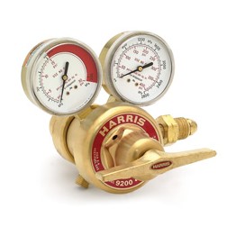 |
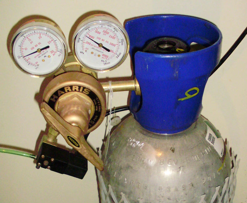
For several months now I have been using a two-stage regulator manufactured for low-pressure industrial applications by Harris (see picture left: Part No. 3302276 Model 9200-15-320 with delivery range 0 to 15 psi).
I am really pleased with it because this regulator has been able to reliably maintain a constant pressure of 5 psi without surging. It is so precise that I do not need to adjust the needle valve to change the bubble rate, which instead can be adjusted by using the pressure adjusting knob. The bubble rate is so stable that I have been able to maintain a constant pH level in the reactor without the need for a controller and without the need to make any adjustment for a couple of months!
On the other hand, if you go for it, and I guess you are already tempted, be prepared to purchase a solenoid and a needle valve separately, not to mention the roughly $300.00 US for this regulator. Note that you will also need some adapters to connect the solenoid and needle valve to the regulator.
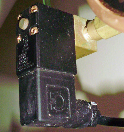 |
Solenoid Valve: A solenoid valve (photo right) is an electrical and mechanical device used for opening and closing the supply of CO2 using electricity. It has two main components: the electrical coil (solenoid) and the valve itself. When it is not powered, the valve is normally closed so there is no CO2 flow. When power is applied, the solenoid turns the electricity into a magnetic field that actuates the stem on the valve to open it.
In general, solenoid valves used in the hobby are very reliable in that they are designed for continually applied power. That is, they are designed for 100% cycle. If it is not designed in this manner, the coil may overheat and fail when continuously powered up.
The most common cause of failure that prevents a solenoid valve to operate properly is having saltwater back-flowing into the valve. Once the water evaporates, it leaves salt deposits inside the valve and, besides corroding the components, will prevent it from operating properly. To prevent back-flow from occurring, a high quality check valve should always be used between the regulator and the reactor.
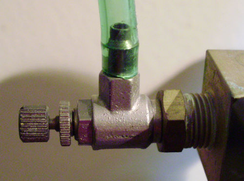 |
Needle Valve: The needle valve (photo left) is a manually operated miniature valve designed to provide small adjustments to the carbon dioxide’s flow. In order to provide for small changes in flow, the stem is shaped like a needle so it provides just a small change in orifice aperture when it is turned. The more turns needed to open the valve fully, the more precise the valve will be.
What to look for in a regulator assembly… Look for sturdiness and as many bronze components as possible, because steel parts will usually corrode over time if accidentally splashed with saltwater. Look for one with a large diaphragm diameter, usually indicated by a larger diameter body. The larger the gauge’s faceplate, the easier they will be to read, and usually, the more accurate they are. Two inches diameter gauges are my minimum preferred standard. As with the cylinder valve, insure that the fitting for the cylinder matches that required by your region of the world.
 |
There are some regulator models available that come with a pre-set delivery pressure and without a pressure adjusting knob; these were usually preset for around 40 psi, which in my opinion makes flow adjustments with the needle valve too sensitive and difficult to achieve. Some new versions, though, come preset at around 15 psi, so if you are getting one of this type, just insure you are getting the lower pressure version. Regardless, my preference is still for being able to adjust the pressure. For safety’s sake, I also prefer to be able to close the regulator using the adjusting knob (see below safety precautions). Hence my preference in using a regulator with a pressure adjusting mechanism.
Most hobby regulators already come with an integrated solenoid valve and needle valve and some also include the bubble counter, although if your reactor is fitted with a counter, this counter may become redundant. Look for a regulator fitted with a good quality and precision needle valve; it will make your job much easier in the long run. Finally, do not forget that a good CO2 check valve (photo above right) is also required to prevent water from the reactor to flow back into the regulator through the CO2 line.
 |
Because the regulator, solenoid and needle valve are subject to the same high pressure the cylinder is, certain precautions are also required, and they are listed below:
These are what I would term “nice to have” items but not strictly necessary. Here is a list of some of my favorites:
This is an electronic device that measures either the pH of the effluent or the pH inside the reactor chamber or in the recirculation loop so that, when a certain pH reading previously set is reached, it either opens the solenoid valve (at high pH) or closes the solenoid valve (at low pH). Check Shoprite Specials and Spar Specials. This device can make the amount of CO2 easier to control, especially if the regulator or needle valve is not precise enough to maintain a very stable CO2 bubble rate.
 |
Some considerations regarding pH controllers:
The controller can not only be used to control the CO2 ON or OFF states, but if you have a stable CO2 flow, then you can use the controller as a safety measure to only close the CO2 in case that for any reason the pH drops too much. In this case the solenoid is always open and closes only when a too low of a pH is reached. My preference is for a controller that can be set for both a low pH as well as for high pH set points by providing an adjustable span of control (the difference between the high and low pH set points) so you can adjust its responsiveness. Also, the controller should be capable of being calibrated not only for a single reading point (calibration) but also for a second reading point (the slope), thereby providing for more accuracy throughout the full range of readings. Follow the manufacturer’s recommendations on how to calibrate, connect and set the controller.
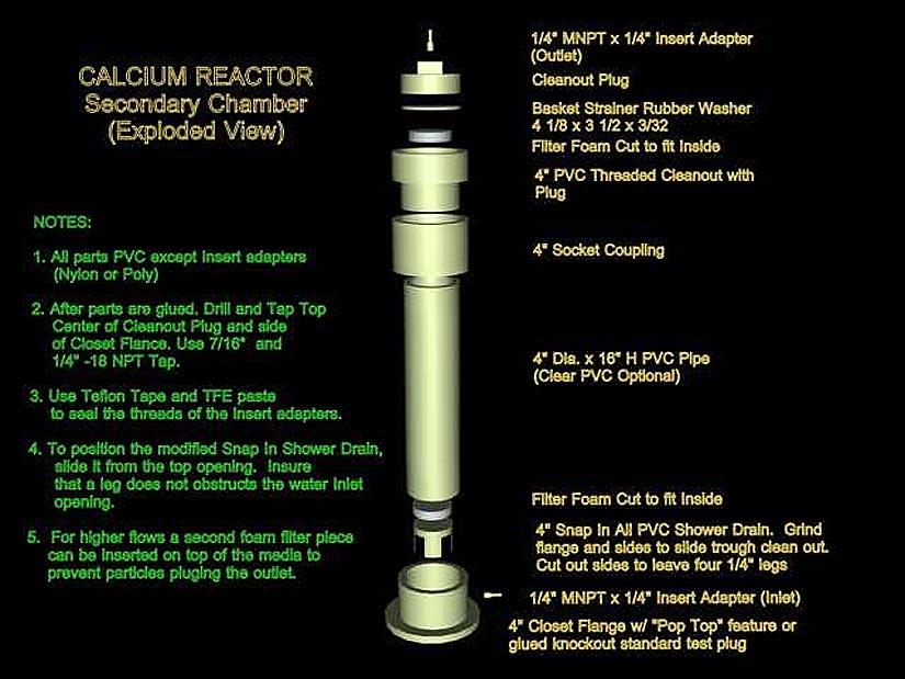
This consists of a second cylinder that is filled also with calcium carbonate media. The effluent leaving the first chamber is passed through the second chamber (usually up-flow) before being returned to the aquarium. This will help improve the calcium and alkalinity saturation by helping to convert more carbonic acid into bicarbonate, and as a result, increasing the pH level in the water leaving the reactor. This helps to reduce the pH lowering effect created by the use of the reactor.
The reactor can be fitted with a second chamber directly from the manufacturer or the second chamber can be purchased separately. If you are a good do-it-yourselfer, you can also build one yourself (see Diagram 4 below).
 |
Note that when using a second chamber in combination with a controller, the pH probe of the controller should be installed in a way to measure the pH of the water in the first chamber or in the recirculation loop. Reading the pH of the final effluent will greatly reduce the controller’s responsiveness because by the time a change in pH is detected at the effluent, the change of pH in the first chamber could already be way out of range.
If your two-chambered reactor does not have a means to install the probe in the first chamber or the recirculation loop, you can easily build a probe sump or chamber that you can install between the first chamber and the second chamber of the reactor, which would allow measuring the pH of the effluent from the first chamber (see Diagram 5 below).
 |
 |
The typical means of measuring the effluent’s flow is to use a small measuring cup and a stopwatch by catching the amount of effluent delivered for one minute. This works pretty well but is a bit cumbersome. A better way of continuously measuring the effluent flow is by using a flow meter. A flow meter is a calibrated glass or acrylic tube that has an internal float which rises with the flow. The higher the flow, the higher the float will rise, thus providing a continuous visual indication of the amount of flow passing through it.
An excellent flow meter for this purpose is the Gilmont unshielded direct reading glass flow meter. It has a glass float and a flow tube size of 13 with a range of 2 to 300 ml/min (around $110.00 retail). A cheaper alternative could be the Dwyer acrylic meter RMA-33 (10 to 110 ml/min) or the RMA – 34 (20 to 300 ml/min). Unfortunately, the short scale of the Dwyer can make it less accurate and more difficult to read, but it will still provide a good reference.
D) Connectors and Tubing:
A reactor fitted with quick John Guest® connectors and in-line subminiature couplings can really make maintenance and setup really easy. You can combine the use of John Guest® connectors with the use ¼” diameter poly-tubing for feeding water to the reactor and for most of the reactor effluent handling.
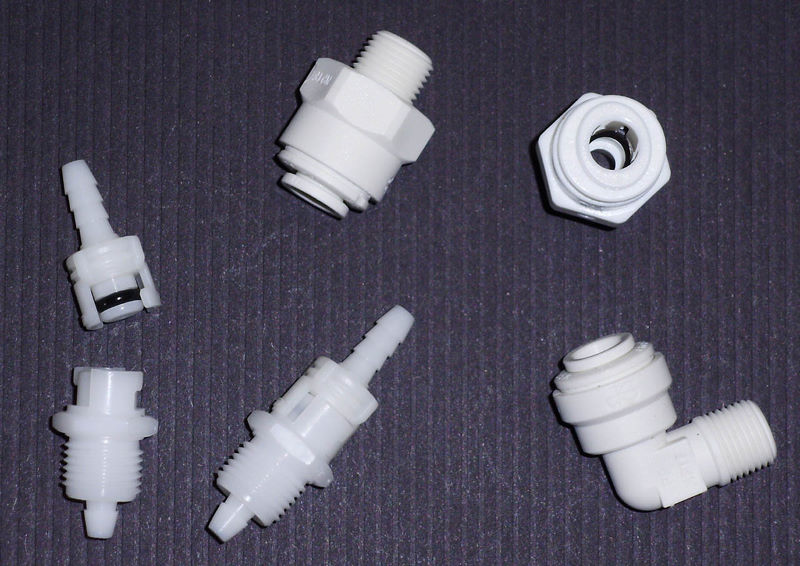 |
Note that for CO2, not all tubing is created equal. Some materials become brittle or CO2 can diffuse trough the tubing walls. It’s important to insure that the tubing used is specified for carbon dioxide use.
There are other accessories like pressure gauges to measure the pressure in the chamber, water pre-filters and CO2 diffusers, but in my experience they really do not provide much of an advantage.
Together with power, CO2, and your alkalinity test kit, calcium carbonate media is the fourth consumable for the reactor. The media could be either pure chemical calcium carbonate, or more typically, it is media that is quarried out or collected from old carbonate deposits formed by coral skeletons.
Calcium carbonate can take two different crystal forms. Calcite, which is usually the form in marine shells of clams, oysters, snails etc. and aragonite, which is usually in the form of coral skeletons and some plants such as Halimeda. Look for aragonite media, as it is easier to dissolve and does not require a very low pH to do so.
 |
Keep in mind the size of the media grains. As mentioned before, the smaller the grains, the faster the dissolution, but also the higher its tendency to plug and reducing the recirculation flow. It is my preference to use large-sized media in the reactor’s main chamber and small-sized media for a secondary chamber, if in use.
Although a lot has been said in the past regarding the purity of reactor media, in my opinion, most if not all commercially available media today meets the purity required for aquarium use. As an example, in my tests of two of the most popular medias using a colorimeter, the level of phosphate detected in the effluent was a maximum of 0.02 ppm, which is below the minimum of 0.03 ppm recommended for the aquarium water, and it is way below the amount contained in the food you would add when feeding your fish and corals. For this reason, the addition of a phosphate removing reactor after the calcium reactor is not only not necessary but may even be detrimental because the high content of alkalinity and calcium in the effluent will rapidly create calcium carbonate precipitate on the phosphate removing media surfaces.
Finally, in order to provide not only calcium and alkalinity, but also magnesium, some magnesium carbonate media (dolomite) could be added to the reactor. If you do so, only about 10% of the total media is needed. Note that the magnesium carbonate media is more difficult to dissolve, so it will require running the reactor at a lower pH than you otherwise would. I no longer use dolomite in my reactor because lowering the pH too far increases the pH lowering effect of the reactor on the system and increases the tendency to turn calcium carbonate media into mud. Additionally, it is easy to supplement magnesium by other means.
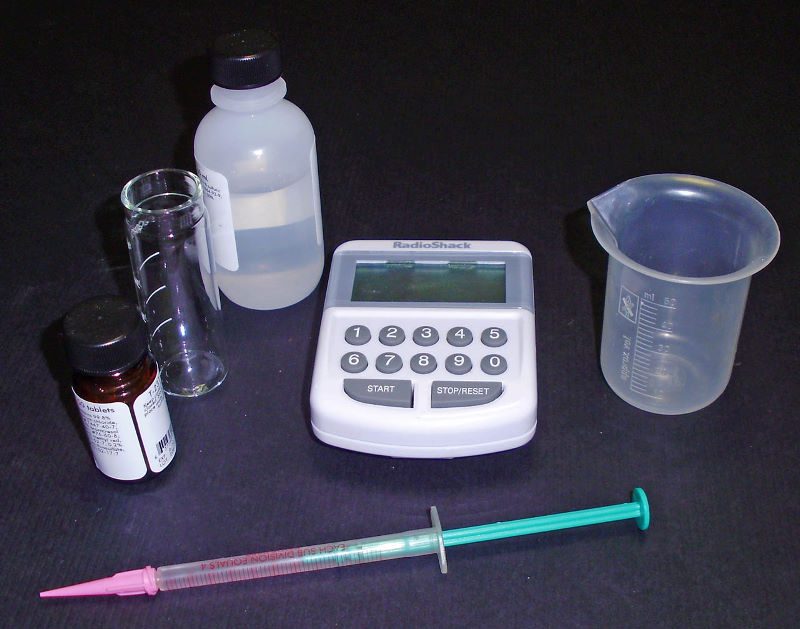
If you will not be using a controller, you will need a pH monitor because a pH chemical test kit or strips are not accurate enough to measure the effluent’s pH. You will also need a good alkalinity test kit, a small 100 ml plastic measuring cup and a stopwatch to measure the effluent flow if you will not be using a flow meter. Depending on the type of bubble counter, a plastic syringe will become handy for filling the bubble counter.
 |
If your bubble counter is installed in the regulator, you can use pure glycerin for the bubble counter; it will make the CO2 bubbles rise more slowly so it will make them easier to count. You can get the glycerin from your nearest pharmacy. I would not recommend using glycerin in a bubble counter mounted in the reactor as there will be greater chance of it mixing with the aquarium water, especially if the bubble counter is designed to be auto-filled when the reactor is in operation.
Check back here next month when I'll discuss setting up your reactor and its associated equipment, adjusting the reactor to match the system's calcium and alkalinity demand and how to perform the needed regular maintenance on your reactor. To wrap the article up, we'll also review some troubleshooting guidelines in the event you encounter some difficulties along the way.
If you have any questions about this article, please visit my author forum on Reef Central.
![]()